From Russia with "Vibrato" - The Kazan Tremolo Pedal
Last updated 07/21/23
By Paul Marossy
The Kazan Vibrato pedal is another unusual and interesting Russian made guitar pedal that I stumbled upon while on ebay/Reverb. It is a companion to the Kvaker wah pedal and the Kazan
"Booster", which is really a pretty gnarly fuzz pedal. This time the seller was in Kazakhstan, so I had to wait 48 days for it to arrive from half way around the world - at the time of writing this the Ukraine still was in the middle of a war with Russia. I thought maybe it would never get out the country but it did eventually make it to me after finally arriving in the USA. Interestingly shipping was via China but that also makes sense. Having been manufactured in 1981, it is also kind of cool as a cold war relic.
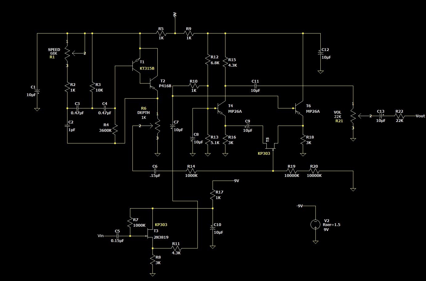
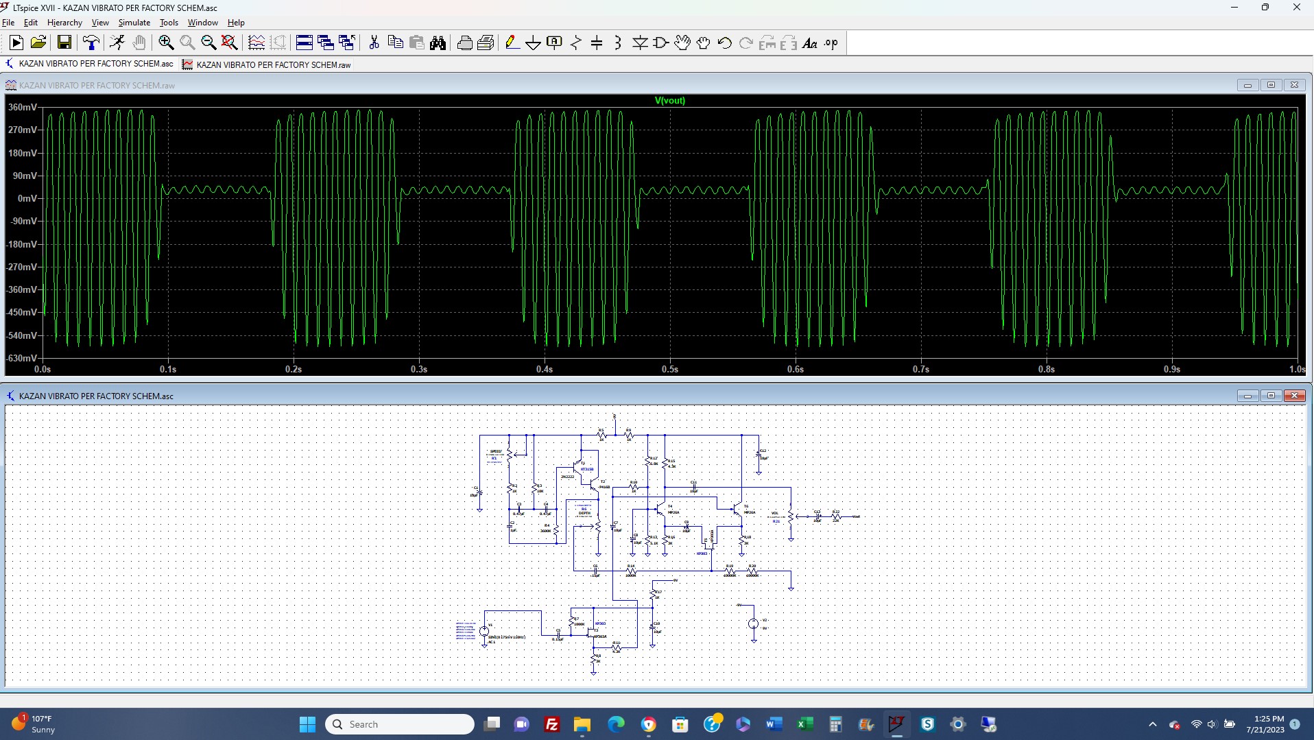
As a tremolo, I think it sounds great. The circuit is interesting. They carry on the Fender tradition of calling tremolo a vibrato. This tremolo circuit utilizes three germanium PNP transistors and two FETs, one of which appears to be acting as variable resistor, creating the tremolo effect. The other FET is at the input of the circuit. The one NPN transistor present in the circuit, the KT315, apparently was the first transistor in the USSR to use planar technology. The schematic below is the one I generated with LTSpice per the factory schematic. The factory schematic can be found in the user manual linked at the bottom of this page. The one schematic I did find on the internet has some errors. Note that it is a "positive ground" circuit.
The enclosure is exactly the same as the Kvaker wah pedal but the bottom plates are different as they have to accomodate a larger circuit board. Weight is also the same, 2.2 pounds and is fairly substantial at 11"x4.3" - it's nearly as large as the Maestro Boomerang but is a little more sleek. They originally sold for 24 Rubles, which is
substantially less than the Kvaker wah. The vibrato sounds very good, and you can use it do tremolo swells kind of like how you would use a volume pedal to make the notes "bloom". The treadle turns a pot which is acting as a depth control. There is no bypass switch - heel down is basically bypass mode and toe down is a pretty choppy vibrato
with a fairly nice range in between. If you can get your picking in time with tremolo it is also possible to do some fiddle and/or cello-like things with it.
Below are some details of the Kazan Vibrato wah pedal.
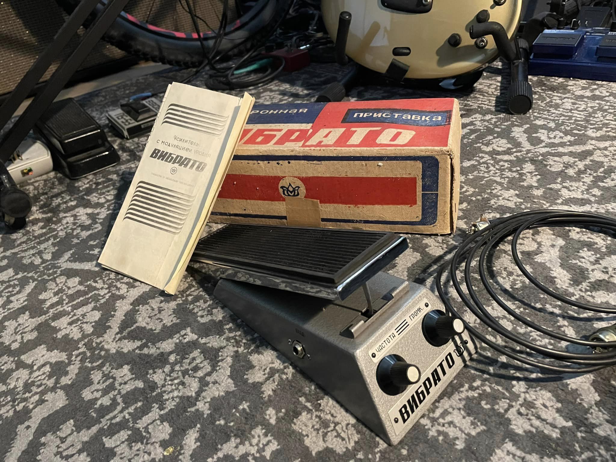 |
This is a NOS unit. It came in a box that is the worst quality cardboard I have ever seen. I'm surprised it has lasted all these years. Inside the box came the pedal, a 5-pin DIN style cable and the owners manual. |
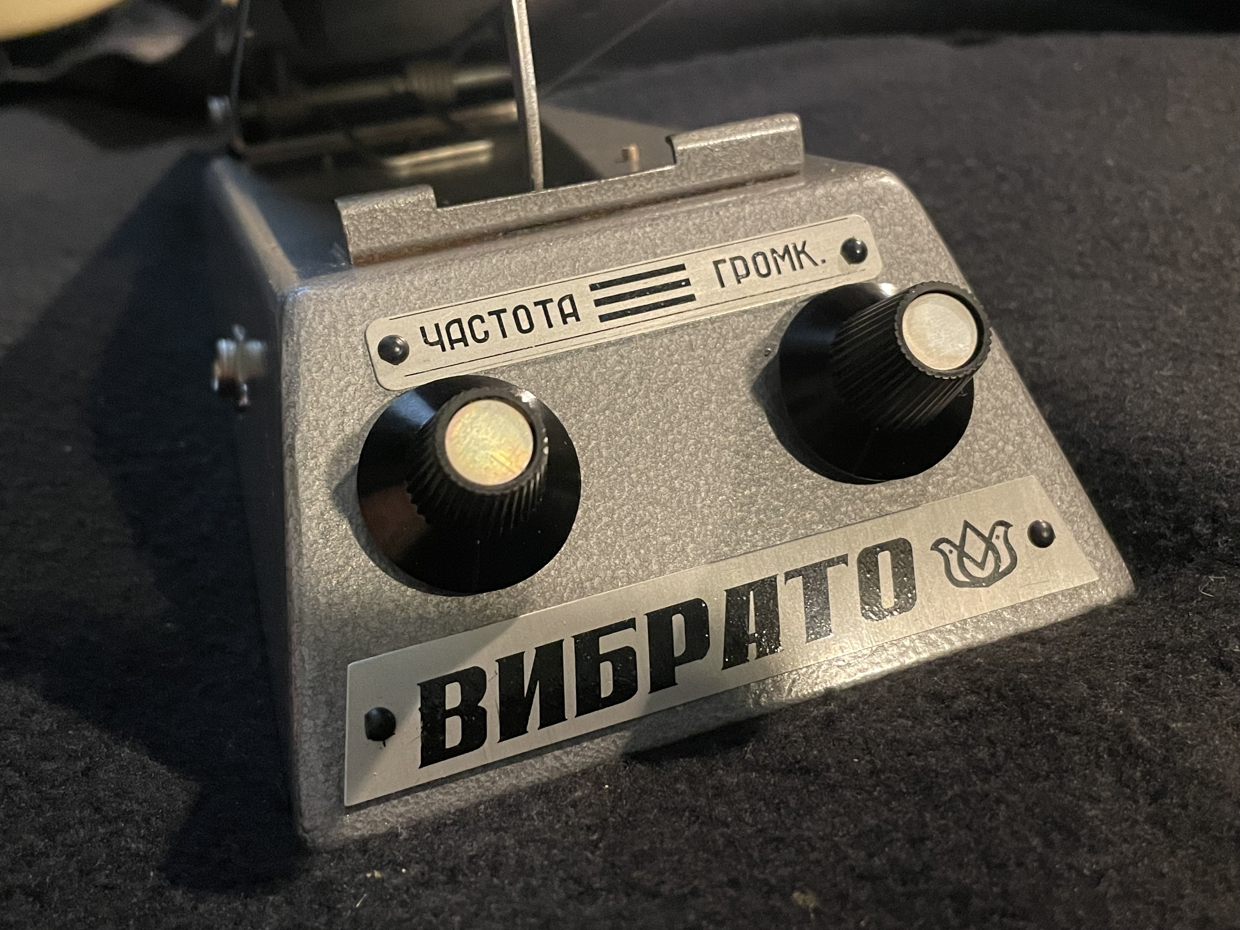 |
The front of the unit has two controls. On the left is Frequency and on the right is Volume. It has a pretty healthy output. The tremolo ranges from 3 Hz to a pretty fast 12 Hz. |
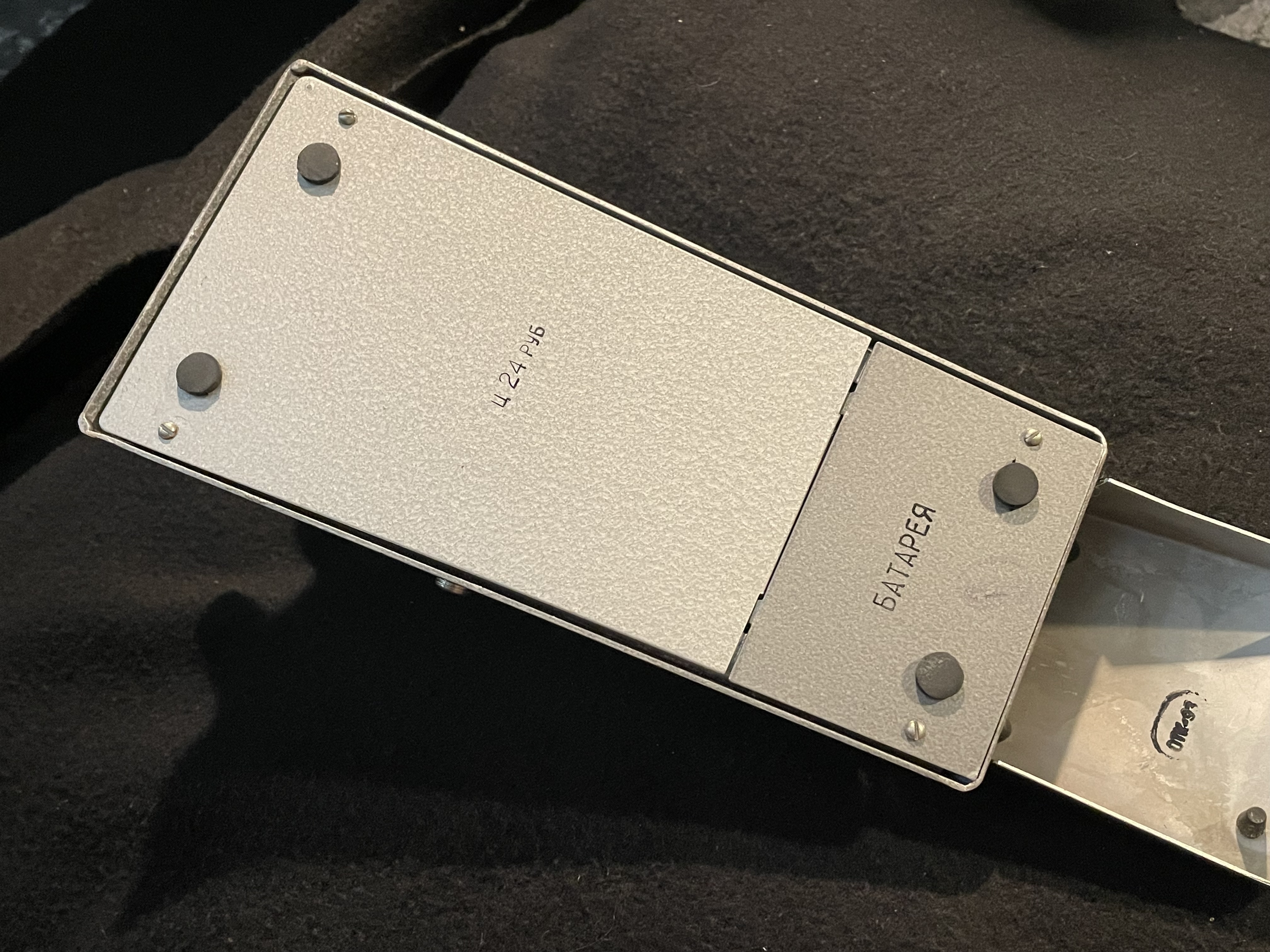 |
The bottom is covered by one large plate and a smaller one under which the 9 volt battery resides. |
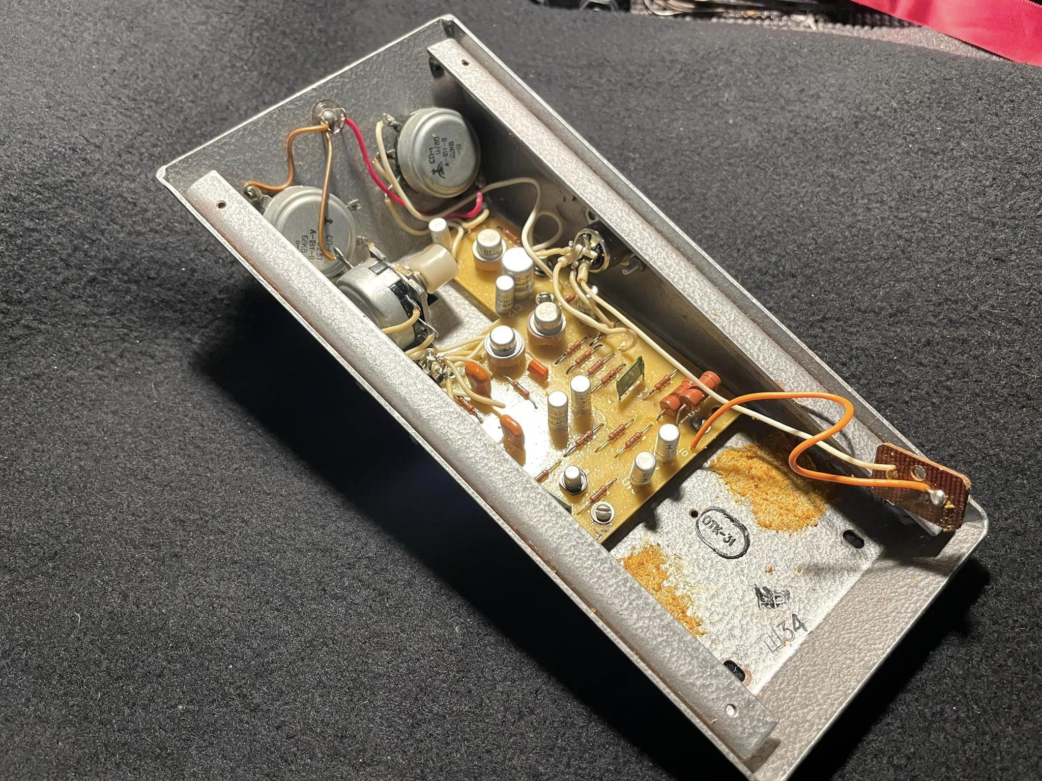 |
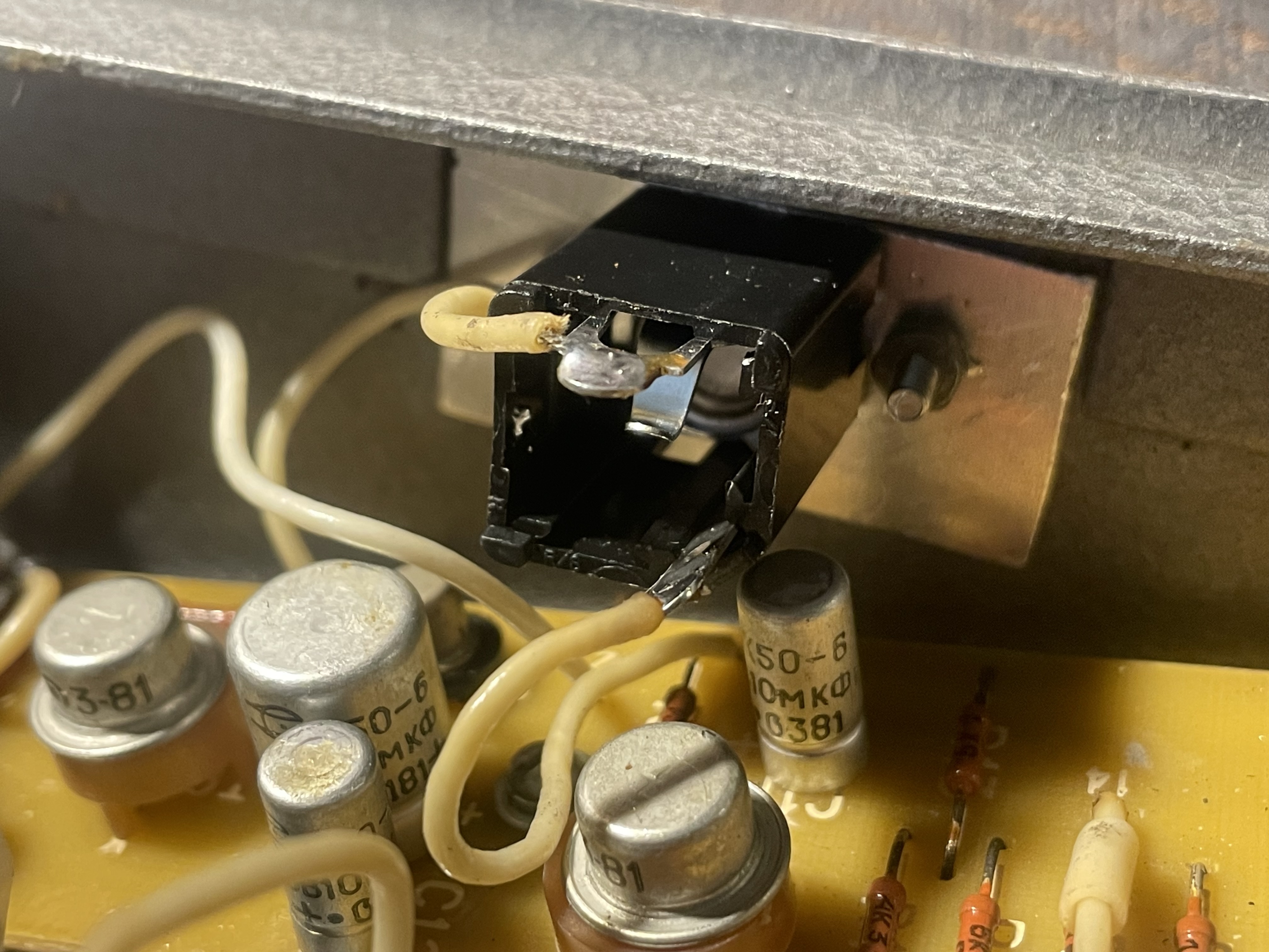
Here is a look inside the housing with the treadle removed. Several germanium transistors can be seen. Uses the same claw & hook actuator arrangement as the Kvaker wah pedal. |
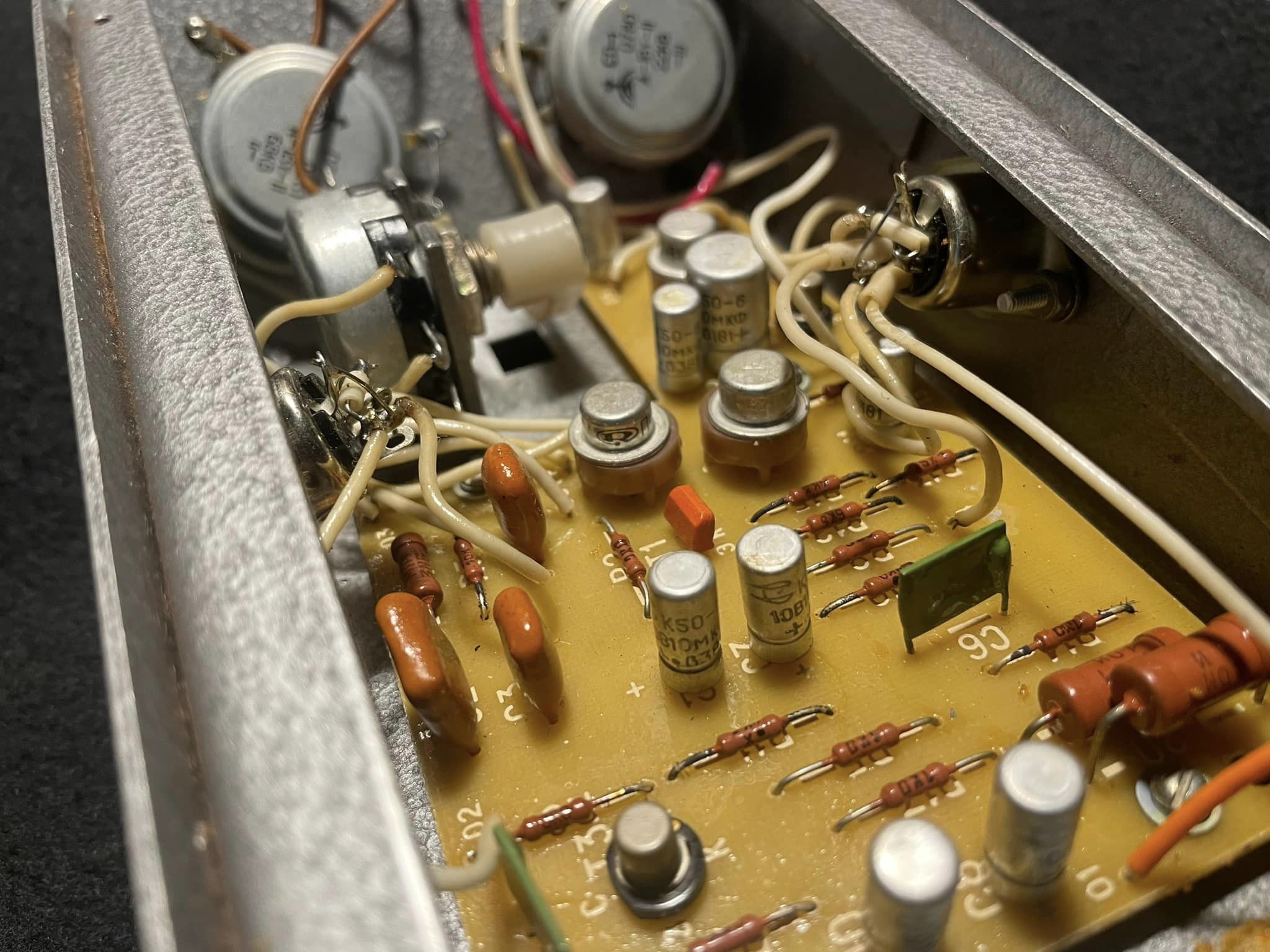 |
This is a little closer view of the circuit board. You can some of those UFO shaped transistors that Russian transistors seem to favor at the time. I'm not sure that they are equivalent to any of the standard package types used in the USA at the time. They have a distinctive look to them. One task I had to do when I received the pedal was to convert the 5-pin DIN jacks to the 1/4" type used today. |
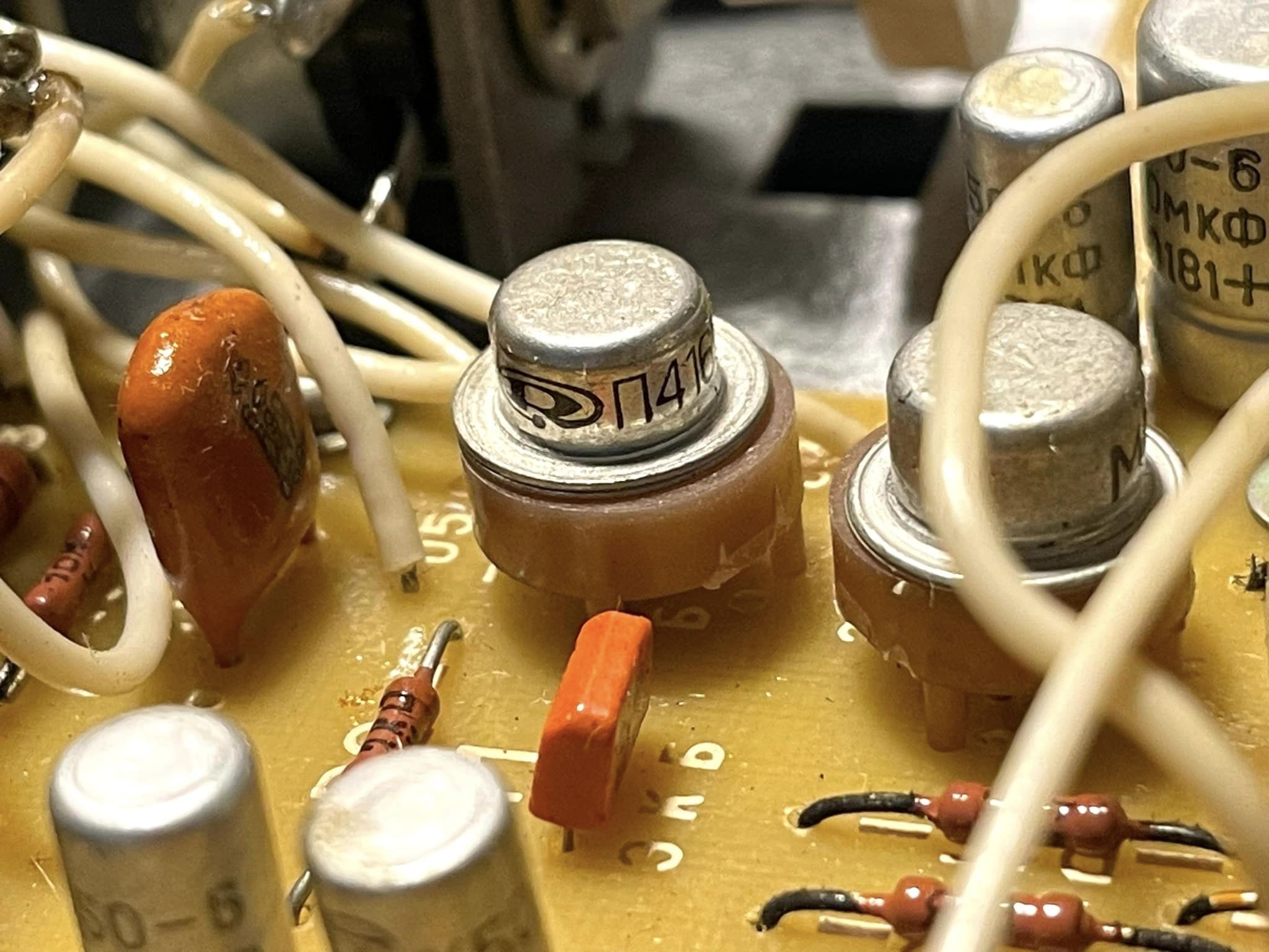 |
Close up of one of the transistors, a P416B. That orange component in front of it is a transistor, a KT315. |
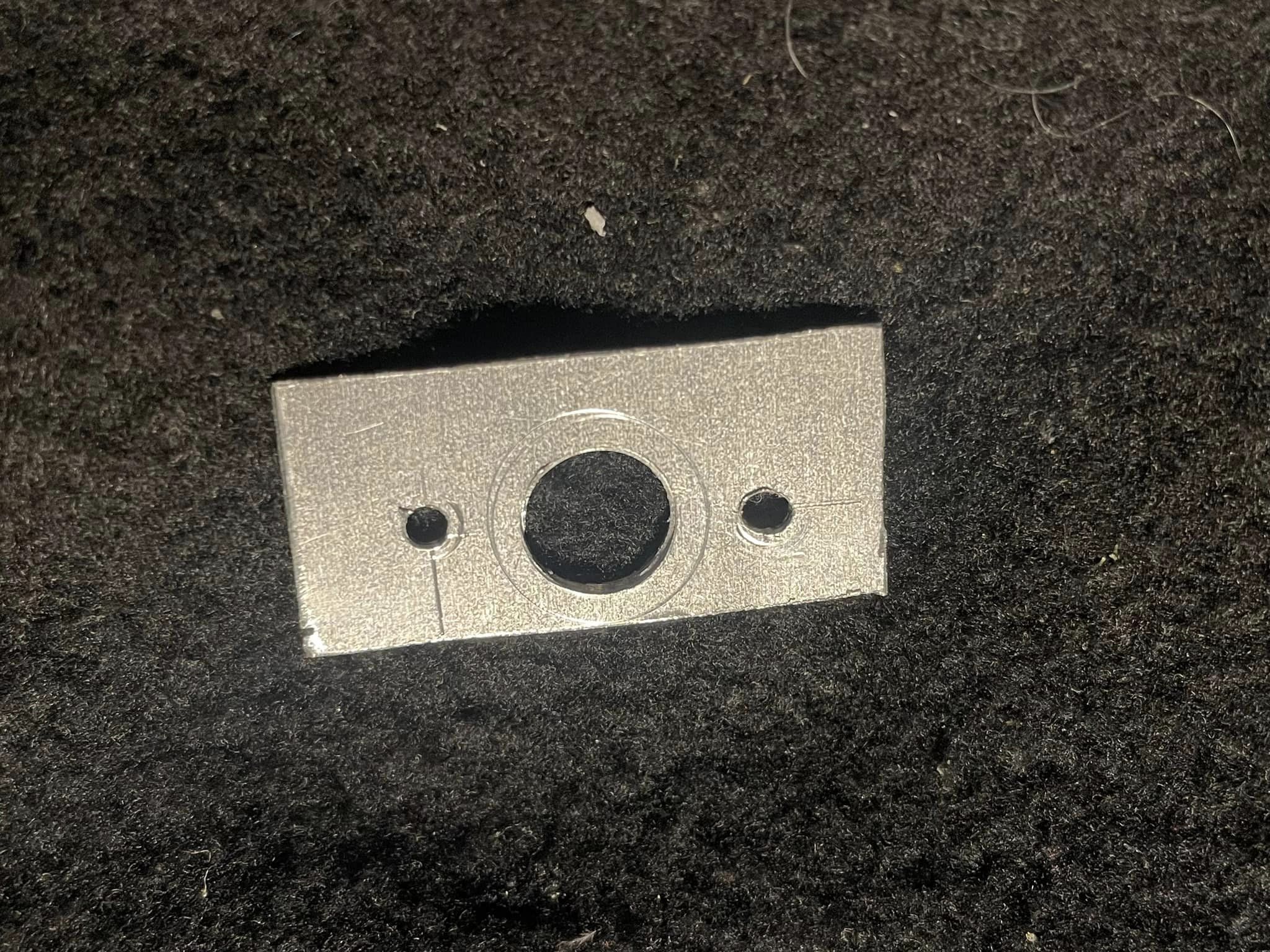 |
Here is one of the two adapter plates I created to convert the original 5-pin DIN input & output jacks. They were easy to make out of a couple pieces of scrap aluminum that are about 1 mm thick. |
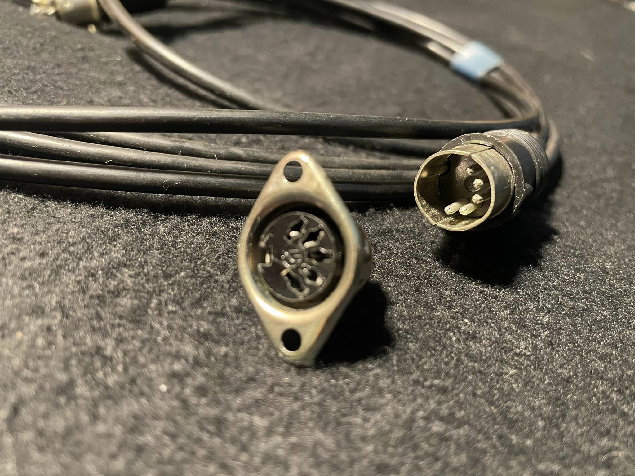 |
Here is one of the original 5-pin DIN jacks with the original cable. Seems like an odd convention to me but all Soviet era Russian musical equipment at the time seems to have used these type jacks. |
 |
Here I have the original input & output jacks replaced with 1/4" types. There was just enough room for them to fit without tweaking anything on the circuit board. The Kvaker wah pedal I bought already had this done. It was a little confusing dealing with these jacks but with the help of the schematic I was able to figure it out. While I was at it I also changed it so that the input jack switches the power instead of the output jack. |
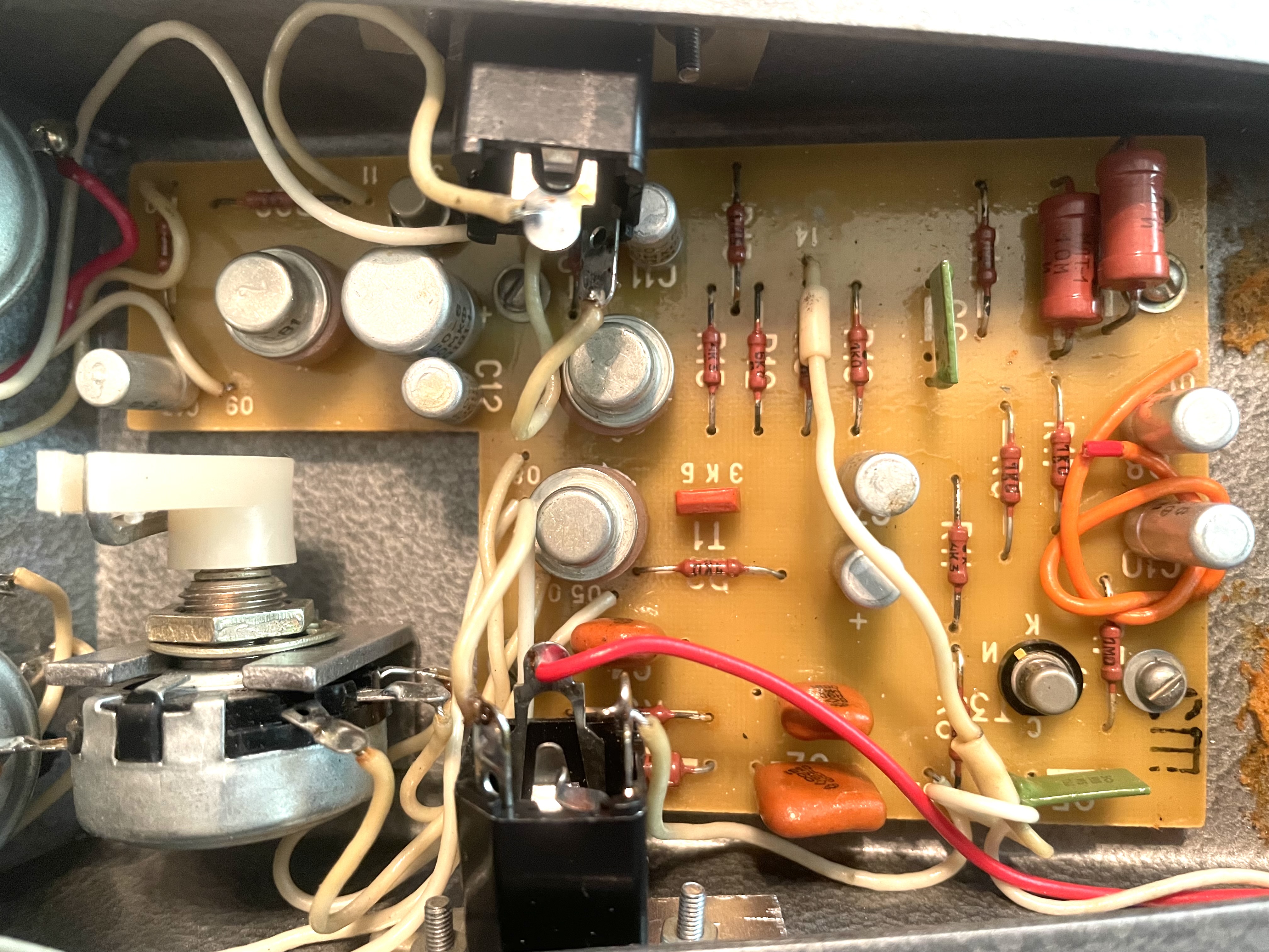 |
Here is a view of the PCB after re-wiring the input & output jacks. |
Overall I think this is really a very cool effect to have. It suits the type of things I like to do when I play guitar. It seems that there are
very few of these units in the USA. There is one more now.
LTSpice simulated this pretty close to what I saw in the real world with an oscilloscope. Shown here is with the depth control at maximum effect. It sounds
pretty choppy in that position. Interestingly, when I was observing waveforms on the oscilloscope, I noticed that with a larger amplitude sine wave at input the circuit exhibits asymmetrical clipping - the postive half of the waveform gets flattened and the negative half stays rounded. The LTSpice model reproduces this pretty accurately too.
So does this circuit work? Here is an explanation of the circuit in operation from R. Strand:
T4 operates as a common base amp. The JFET (T5) resistance forms a divider with the low input impedance at T4's emitter. That's the primary tremolo mechanism. The voltage on C8 remains fixed. C8 and the two voltage divider resistors act like a Vref circuit on an opamp pedal except it biases the base of the two transistors T4 and T6.
The JFET (T5) acts like a variable resistor. When the sine wave output from depth control is more positive the JFET is on and the signal passes. When the depth is off the gate is actually forward biased and the JFET is fully on. So the small detail is when the sine wave from the depth control swings positive it also forward biases the gate and passes the audio signal. What happens through is once the oscillator has been running for a short time, the cap C6 charges up through the gate diode of the JFET on the positive peak of the sine-wave. At the positive peak the JFET is fully on (just). That means the negative swing of the sine wave the JFET is driven off. That's how you get the modulation.
The EA tremolo works in a similar way in that there is a cap between the JFET gate and the oscillator output. In the case of the EA it's the cap between the oscillator and the depth pot.
The charging cap means the biasing on the emitter of T6 *isn't* that critical. It's actually the negative voltage which drives the JFET on when the depth is on zero.
The advantage of the C6 charging on the oscillator peaks is the only thing that changes with different JFETs is how far you have to crank the Depth control to get the signal to pinch off (the dips in the modulation). A low VP JFET requires a lower Depth setting than a high VP JFET to get the same amount of pinch-off. From what I can see with a few different JFETs is the depth control for pinch-off is somewhere between half and full. If you look at T3, it looks like a buffer, *but* because of the positive ground it's actually a gain stage. Technically the drain and source are drawn reversed but it still works because JFETs work with d and s swapped.
Kazan Vibrato Original User Manual